Sign In


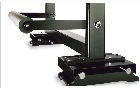
Unwind/Rewind Stands
Fife developed the Shifta-Roll stand to accommodate or replace many existing roll stands that would not lend themselves to the application of automatic guiding equipment. All Fife Shifta-Roll stands are easily adaptable to existing or new machinery to accurately position the unwind or rewind roll.
Unwind guiding ensures the correct edge alignment to a predetermined guide point. Depending on the sensor selected, unwind guiding sometimes requires a direct mounted or slave idler or idlers for proper operation. The idlers are required when using a sensor with a narrow gap or a line guide sensor. The idler maintains a constant plane for the material being guided. The unwind stand is generally positioned so there is less than one web width to the first fixed idler in the machine.
Basic operation of an unwind guide (as illustrated in figure 1): The operator positions a roll of material on the unwind stand. The operator then positions the sensor where he wishes the edge of the web to be positioned. In automatic mode, the unwind stand then shifts laterally, keeping the edge of the web at the guide point of the sensor. The ideal location for the sensor is as close as possible to the shifting unwind. This will give the best dynamic performance and accuracy. Systems are available that allow the sensor to be located after the first fixed idler. These systems will guide the web, but at a reduced performance.
Rewind guiding is not truly lateral control of a web. Rewind guiding is actually a chasing control system. The rewinding roll is positioned to align the edge of the rewind roll to the edge of the approaching web. The sensor is located just ahead of the last fixed idler in the machine and is typically attached to the rewind stand with a mechanical arm. The sensor chases the edge of the web and, as a result, the rewind is laterally positioned directly downstream of the incoming web. Systems are available that do not require the sensor to be mounted to an arm attached to the rewind stand. The sensor is electronically connected to the rewind stand. The rewind stand is generally positioned so there is approximately one web width from the last fixed idler.
Basic operation of a rewind guide (as illustrated in figure 2): The operator either manually or automatically positions the sensor at the edge of the web being chased. The rewind control system then causes the rewind stand to shift laterally as the web tracks laterally, resulting in a roll of material with a straight edge.In rewind guiding, if the sensor is located downstream of the last fixed idler or the web does not have sufficient frictional engagement with the last fixed idler, a roll with a ragged edge will be wound.
Another problem often seen in rewound rolls are telescoped wraps. The guiding system is often blamed for this defect, when in reality, the roll was not wound with sufficient tension to prevent lateral slippage of one or more layers in the wound roll. This defect often occurs many wraps inside of the wrap being applied, during winding or up to days after the roll is removed.